
Addressing the impacts of changing regulations and feedstocks in sulfur recovery units
The efficient and reliable operation of sulfur recovery units (SRUs) continues to be critical to hydrocarbon processors, which are tasked with delivering end products that contain lower levels of sulfur while simultaneously reducing the amount of sulfur that is emitted to the local environment. In January 2020, the International Maritime Organization’s initiative to lower pollution from ships – often referred to as IMO 2020 or MARPOL 2020 – represented the most recent global regulatory requirement on an end product that directly affected refiners. This change lowered the available H2S content in fuel oil from 3.5% to 0.5%, driving ever greater removal of sulfur components in processing operations and higher recovery efficiency of elemental sulfur (SX) in SRUs. Local and national jurisdictions are continuously reviewing and modifying emission maximums, further impacting the design and operation of SRUs.
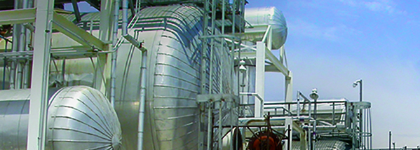
As a reminder, an SRU is tasked with one primary objective – to recover some amount (often 96+%) of the elemental sulfur that has been delivered to it. Hydrocarbon feedstocks that are used in most natural gas processing facilities and refineries contain sulfur that must be removed. The sulfur contains very little energy value and, more importantly, can negatively impact final product purity requirements. There is a positive element to recovering elemental sulfur however, as it can be sold and used in fertilizer and medical drug production. During hydrocarbon processing, sulfur components can be stripped out of the feedstocks using combinations of catalysts, temperature, pressure, and the introduction of excess hydrogen, and sent to the SRU for elemental sulfur removal. The gas streams delivered to the SRUs are typically referred to as acid gas and/or sour water stripper gas and, unfortunately, frequently consist of components other than just ‘sulfur compounds’, which will be touched upon later in this article. Upon entering the SRU, the feedstocks undergo a modified Claus reaction to have SX removed. The gas enters a reactor furnace, continues through a series of converters and condensers – where the elemental sulfur is captured – and then either enters a tail gas treatment unit (TGTU) before being burned in a thermal oxidizer, or the TGTU is either bypassed or not required and the gas stream is burned in the thermal oxidizer before exiting the SRU via a stack (Figure 1).
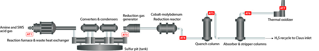
Figure 1. Typical SRU layout, with common analyzer locations
Feed gas analysis (AT1)
Gas streams entering the SRU are often referred to as ‘SRU feed gas’ and are complex as they can include many different components at varying concentrations. It should be remembered that the feed streams entering the SRU are a result of prior processes – stripping and hydrotreating. As such, they can be impacted by changes in the plant feedstocks and process upsets, resulting in significant changes to their make-up. Hydrogen sulfide (H2S), carbon dioxide (CO2), ammonia (NH3) and ‘hydrocarbons’ (THC) are the most common constituents, with H2S having the highest expected concentration.
In the reaction furnace, the SRU feed gas is mixed with air or pure oxygen and heated to produce sulfur dioxide (SO2). This is shown in reaction 1 below. The SO2 will then react with H2S in the converters and elemental sulfur will be produced, see reaction 2 below.
Modified Claus reaction (heat)
3H2S + 3/2O2 ---> SO2 + 2H2S + H2O (1)
SO2 + 2H2S ---> 3/x SX + 2H2O (2)
Historically, SRU operators attempted to maintain a strict 2:1 ratio of H2S:SO2 to ensure reliable operation and high SX recovery. With different licensors and users constantly modifying their equipment and processes, the actual H2S:SO2 ratio may be different than 2:1. In any case, designers and users do strive to maintain a proper ratio of H2S:SO2 throughout the converters and condensers. A process engineer can see how important it is to control the flow of feedstock into the SRU or the amount of air/oxygen injected to maintain a proper ratio. Experienced SRU engineers know that management of feedstock and oxygen flow rate is not too difficult when the incoming components and concentrations are consistent and known. Issues arise when the feedstock begins to vary.
When hydrocarbon concentrations are suddenly changing, the impact on the SRU can be significant. The hydrocarbons consume more of the available oxygen, reducing the amount of H2S being converted to SO2 in the reaction furnace. From Figure 2 and Table 1, it can be seen that the amount of oxygen being introduced to the reaction furnace needs to increase as more hydrocarbons enter the reaction furnace and reduced as the hydrocarbons ‘go away’.
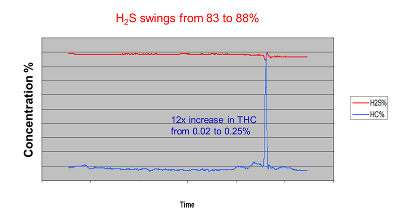
Figure 2. The sudden increase in hydrocarbons entering the SRU results in an increase in H2S after the final condenser. SO2 concentrations would decline, and the desired ratio would not be met.
|
Compound |
Moles O2 per Mole HC |
Ratio of O2 needed per mole HC compared to per mole H2S |
|
Methane |
2 |
4 |
|
Ethane |
3.5 |
7 |
|
Propane |
5 |
10 |
|
Butane |
6.5 |
13 |
|
Pentane |
8 |
16 |
|
Hexane |
9.5 |
19 |
Table 1. Hydrocarbons “steal” the O2 intended for H2S to SO2 conversion
Some SRU professionals have said that problems arise not when the hydrocarbons come in, but rather when the hydrocarbons suddenly go away. What they have experienced is that the excess oxygen being introduced into the reaction furnace results in excess SO2 formation. This results in SO2 breakthrough to the TGTU, causing damage to the amine found in TGTU absorber. Costs of US$40 – 50/liter are common for specialized amines, so damages not only result in possible plant shutdown or TGTU bypass (higher SO2 and H2S emissions will need to be reported), but also increased operational expense.
Conversely, SRUs that have extremely efficient converters and condensers, or lower recovery requirements, may not have a TGTU present. For these applications, end users have noted that a sudden increase in hydrocarbons requires operators to get on the air in the incinerator (thermal oxidizer) to prevent a temperature condition at the emission stack.
AMETEK has a dual analytical bench analyzer that is specifically designed to measure the incoming SRU feed gas components and their concentrations. The IPS-4 analyzer utilizes both an ultraviolet (UV) and infrared (IR) bench to measure in real time the components and concentrations, and houses a fit for purpose sample conditioning system in one enclosure. Coupled with a double block heated acid gas (HAG) probe, the IPS-4 Feed Forward solution has been installed at SRUs around the world.
Tail gas/air demand analyser (AT3)
A tail gas or air demand analyser is located after the final condenser and is present in nearly every SRU. Measurements here are often referred to as ‘feedback control’, as they provide feedback on the (nearly) final product. This feedback control is responsible for approximately 10% of the air/oxygen that is entering the reaction furnace – the remaining 90% is typically designed into the system. Measurement at this point is the most reliable way to ensure the proper ratio of H2S to SO2 has been maintained after the reaction furnace and provides final component concentrations before the TGTU or thermal oxidiser. With such a high installation and utilisation rate, and so many articles readily available on the purpose of the tail gas/air demand analyser, it is only necessary to briefly touch on some key items to consider:
- As previously mentioned, the ideal ratio of H2S:SO2 in the SRU is typically 2:1. Most plants operate with up to 2 – 4% H2S and 1 – 2% SO2 expected at the condenser outlet, but some require lower or higher ranges based on engineered design or sulfur recovery requirements. It should be kept in mind that it may be necessary to use ranges that cover upset conditions, so that operators can get back to proper operations after something unexpected occurs prior to or at the reaction furnace.
- Ensure proper thermal management of the sample gas throughout the analyser system – probe to analyser to return location. SX is unique in that its phase can change very easily when sample handling temperatures are not properly maintained. If the sample temperature is not maintained high enough, the SX can condense as a solid, resulting in blocked sample gas analyzer inlet and outlet lines. If sample temperatures are too high, the SX can go from the desired gas phase to a gelatinous one. This too can result in blocked inlet and outlet sample lines, or contamination of the gas analyzer optical cell. Money spent on a well-proven design will pay for itself in analyzer uptime and reduced maintenance.
- Focus on measurement requirements and not just the technology used in the analyzer. It is important to select an analyzer system that provides the measured components and concentrations that are required and that a team can operate and maintain. It is recommended to search for references within the sulfur community.
Tail gas treatment (AT4, AT5, AT6)
For SRUs equipped with TGTUs, proper analyzer selection and installation can result in high measurement availability (high uptime) and prevention of significant operational expenses when the unexpected occurs. Not every SRU contains a TGTU, as super-efficient conversion and condensing of SX may not require final treating prior to the thermal oxidizer at the emission stack. For those SRUs that do have a TGTU, there are two locations that could most benefit from some type of gas analysis.
TGTUs almost always include a reduction reactor, catalyst – cobalt molybdenum (CoMo) or other proprietary active material, a quench tower, an absorber, and a regenerator. Gases enter the TGTU after having nearly all of the SX removed and, after moving through the TGTU, the gases are sent to a thermal oxidizer before being emitted through the stack with as little H2S and SO2 as possible – exact limits or emission rates are often defined by local environmental requirements.
Between the reduction reactor and the quench tower, gas from the final condenser is heated and mixed with an excess amount of hydrogen – often injected, but sometimes already present in the tail gas – to convert any remaining sulfur components (that are not H2S) to H2S. Formulas 3 – 7 indicate the reactions that take place in the CoMo reactor:
SO2 + 3H2 ---> H2S + 2H2O (3)
S + H2 ---> H2S (4)
H2O + CO ---> H2 + CO2 (5)
COS + H2O ---> CO2 + H2S (6)
CS2 + 2H2O ---> CO2 + 2H2S (7)
Some users have chosen to measure SO2 and/or H2 at this location, AT4 on Figure 1, to ensure that SO2 is not entering the absorber where it is known to damage amine (as previously mentioned). However, for most operations, this location is not ideal. SO2 concentration usually is at a very low ppm level, leading users to question whether the analyzer is reading correctly, the sample often has a high dew point requiring water removal, and is highly toxic. It is known, however, that if a proper amount of excess H2 is maintained elsewhere in the TGTU, SO2 will be converted (formula 3). H2 concentrations do not change much from the inlet of the quench tower to the thermal oxidizer, so users have moved to measuring H2 before and after the absorber instead.
In the quench tower, the H2S in the gas stream is cooled and removed from the TGTU, with the resulting ‘sour water’ often returned to the reaction furnace at the beginning of the SRU. At the t op of the quench tower, commonly referred to as the quench tower outlet, H2 is measured, as little to none should be swept away by the cooling of the quench tower. This is a much more reliable measurement point for H2, as the dew point is usually much lower, making sample handling much easier. Engineers may also measure H2S at this location for material balance purposes or to measure the efficiency of the absorber (absorber outlet H2S/absorber inlet H2S). AMETEK has found that H2 analysis at this location is required for confirmation that the TGTU is operating correctly and that the amine in the absorber is protected from SO2 upsets.
In the absorber, any remaining H2S is removed by amine or other stripper. The stripper is then recycled in the regenerator and the H2S that is removed in the regenerator is again returned to the reaction furnace at the start of the SRU. Gas exiting the ab sorber ‘overhead’ is then directed to the thermal oxidiser. H2S measurement is universal at this point, as it directs sample and air flow rates at the thermal oxidiser prior to final release of the completely treated gas to the stack. The company’s experience indicates users are also measuring H2, carbonyl sulfide (COS) and carbon disulfide (CS2) at this point:
- The H2 measurement at this point is a back-up to H2 analysis made after the quench tower. This redundancy is driven by a desire to confirm that excess H2 has been present, resulting in complete conversion of SO2 to H2S prior to the absorber.
- COS and CS2 measurements help complete the plant sulfur balance calculations, but more importantly indicate an issue with the catalyst found in the CoMo reactor. As the catalyst ages, the COS and CS2 levels will rise (Figure 3).
Figure 3 details two different issues with the TGTU operations. The increase in COS readings indicated a problem with the CoMo catalyst properly converting sulfur species to H2S. After the catalyst was replaced – note 1 week of no analyser readings – the TGTU was started back up and the H2S readings were much higher than expected. The end user subsequently made corrections to their amine regenerator. The net result was that the user was able to properly repair their TGTU, and not shut down the entire SRU to troubleshoot the entire system. This saved time and considerable expense.
One final point to note about the quench tower outlet and absorber outlet measurements is that the sample at these points is extremely hazardous to human life. Use of a heated sample probe that integrates a single inlet and outlet tap and double block mechanism – such as AMETEK’s HAG probe – is recognized as a requirement and not an option.
Continuous Emission Monitoring System (AT7)
Measurements at the thermal oxidizer are driven by regulatory requirements. Many users are required to measure SO2, NOX, H2S, CO, CO2 and sometimes O2 concentrations. Most of the regulated components are going to be present in low ppm concentrations. There are many technologies used by many suppliers of continuous emissions monitoring systems (CEMS), but it is critical to consider where this measurement is occurring. The SRU is constantly handling and converting a gas stream that is highly toxic and corrosive. AMETEK’s experience indicates that careful consideration of potential upset situations leads to design and implementation of the most reliable measurement systems. A system that is designed to handle any SX or SO3 carryover is going to be more complex and more expensive, but maintain a much higher uptime in the SRU than one designed to measure furnace effluents (as an example) elsewhere in the plant. The increased uptime reduces fines from regulatory agencies that can quickly exceed the price difference between a basic CEMS and one designed for purpose. This is another measurement point for which working closely with other members of the global SRU community is recommended, in order to solicit feedback on best solutions and not focus on a specific analytical technology. AMETEK integrates a variety of technologies when asked to provide an SRU CEMS, based on experience and end user requests.
Learn more about AMETEKs solutions for sulfur recovery units.