May 2026
Petrochemical Technologies
Capital efficient ethane cracking: Quantifying the tradeoffs between full recovery and streamlined configurations
Ethane cracking remains the dominant route for producing polymer grade ethylene in regions with abundant natural gas liquids, particularly North America and the Middle East. Ethane’s high hydrogen content and simple molecular structure enable high ethylene yields with low pyoil (cracked bottom product) and C3+ byproduct (C3–C8) formation and minimal byproducts compared to heavier feedstocks. This inherently efficient chemistry leads to lower capital intensity, simpler plant layouts and attractive operating margins, making ethane steam crackers among the most cost-competitive olefins assets globally.
A conventional ethane cracker is optimized almost exclusively for ethylene production. The flow scheme typically includes cracking furnaces (optimized for high ethane conversion and selectivity), primary/secondary fractionation to recover ethylene and minimal byproduct hydrotreating. This configuration minimizes both capital expenditure (CAPEX) and complexity. Byproducts are modest in volume, and the revenue mix is overwhelmingly ethylene driven.
Conversely, to enhance product flexibility or capture additional value from light olefin markets, adding recovery and other processing units might be considered for propylene co-production (via enhanced C3 recovery), pygas hydrogenation to upgrade aromatics-rich C6–C9, and full C3+ fractionation, including debutanizers, depropanizers and associated auxiliaries. These additions allow the cracker to generate considerable quantities of propylene and upgraded pygas, creating a broader products slate and hedging against ethylene market cyclicality. However, they substantially increase plant footprint and both fixed and variable operational expenditure.
Expanding a pure ethylene configuration to a complex olefins/co-products configuration can raise capital cost significantly and must be technically justified. Typical expansions on a pure ethylene configuration include 20%–40% additional CAPEX for full C3 recovery, propylene purification, pygas hydrotreating and higher utility demands. Whether the investment is justified depends on market assumptions. In ethane cracking:
- Ethylene-only plants generally have the lowest equipment count and achieve the lowest cost per ton of ethylene, dominated by ethane supply and strong polyethylene demand.
- Propylene co-production may outperform over the asset’s life if propylene price spreads remain structurally strong, there is demand growth in polypropylene or if there is strategic integration with downstream C3 derivatives.
- Pygas hydrogenation is generally a modest-value upgrade unless the investor participates in benzene, toluene and xylene (BTX) chains or high-specification gasoline blending markets.
Ethane crackers optimized for ethylene remain the benchmark for capital efficiency and simplicity. Adding propylene recovery and pygas hydrogenation offers product diversification and potential long-term margin uplift, but at noticeably higher CAPEX and complexity. The investment becomes attractive when propylene margin forecasts remain structurally positive, or when there is downstream integration within the petrochemical complex.
The decision ultimately hinges on market status. Pure ethylene configurations maximize return on investment in fresh ethane regions, while complex configurations deliver resilience and optionality in diversified petrochemical portfolios. This technical article explores multiple case studies during a project development from a techno-economic perspective, providing insights into how different design configurations influence both project economics and long-term asset performance.
Base Case scheme. The Base Case represents the conceptual configuration per initial requirements of the ethane cracker within the project. In this configuration, the ethane cracker is designed to process ethane feed into 1.8 MMtpy of ethylene, with coproducts including propylene, hydrogenated pygas, C3/C4 recycle, pyoil and fuel‑gas components.
Downstream of the deethanizer, the system sequentially includes the depropylenizer, a C3+ hydrogenation reactor, a debutanizer and a 2nd-stage pygas hydrotreater (PGH), each performing targeted separations and treatments. The depropylenizer recovers polymer‑grade propylene as an on‑spec export product. Its bottoms are routed to the C3+ hydrogenation system, where olefinic and reactive species in the C3+ range are stabilized. The hydrogenated effluent flows to the debutanizer, which splits the stream into a C3/C4 overhead recycle (returned to the cracking furnaces, increasing overall ethylene yield) and a C5+ pygas fraction. This C5+ stream enters the 2nd-stage PGH, producing a hydrogenated pygas suitable for subsequent aromatics extraction.
This configuration (FIG. 1) ensures maximum flexibility and highest product recovery, including stabilized pygas and propylene production. The Base Case also requires associated propylene storage, hydrogenated pygas storage and heavy‑oil/pyoil systems. It is the most equipment-intensive configuration and, therefore, has the highest capital cost baseline in the techno-economic comparison.
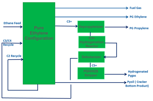
FIG. 1. Base Case block flow diagram.
Optimized Case scheme. This case is a more streamlined ethane cracker configuration that aims to reduce capital cost while maintaining safer and more stable product handling. In this scenario (FIG. 2), the ethane cracker configuration does not contain the depropylenizer, the debutanizer or the 2nd-stage PGH, but retains the C3+ hydrogenation system (with the option to keep one or both hydrogenation reactors). As a result, neither propylene nor hydrogenated pygas are produced, and no C3/C4 recycle is returned to the cracking furnaces. De-ethanizer bottoms flow directly to the C3+ hydrogenation reactor, producing a hydrogenated C3+ byproduct that is a stabilized stream, as diolefins and most of the olefinic compounds are hydrogenated compared with the raw C3+ stream. This hydrogenated C3+ stream is then routed to battery limits for external disposition. With the elimination of C3/C4 recycle, the ethane cracker requires additional fresh ethane feed to maintain its 1.8-MMtpy production rate, though this is expected to offset most internal flow changes and avoids reductions in furnace run length.

FIG. 2. Optimized Case block flow diagram.
On the outside battery limits side, propylene storage is scaled down because the ethane cracker no longer produces propylene. Hydrogenated pygas storage is deleted, and new hydrogenated C3+ storage, typically as a high‑pressure sphere sized for 10 days, is added.
The Optimized Case scheme offers a safer and more operationally robust alternative to other possible flow schemes because the hydrogenation step reduces risks associated with reactive components such as butadienes, acetylenes and diolefins. From a cost perspective, the Optimized Case scheme yields significant total installed cost (TIC) reductions relative to the Base Case, while producing a more manageable export stream.
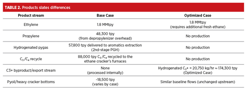
Techno-economic comparison. To understand the economic implications of streamlining the ethane cracking flow scheme, a detailed techno‑economic comparison is required, examining how the removal or retention of key separation and hydrotreating units reshapes the overall design, product slate and feedstock requirements (TABLES 1 and 2).
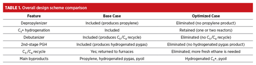
The evaluation of multiple design configurations for an ethane cracking facility demonstrates that the choice between a full‑recovery case and a streamlined Optimized Case is fundamentally an investment-driven decision shaped by product strategy, capital constraints and downstream integration. The Base Case provides the highest product recovery, capturing propylene, hydrogenated pygas and valuable recycle streams. However, the Base Case has a greater capital intensity, a higher equipment count and increased operational complexity. Its value proposition is strongest when markets favor propylene and aromatics feedstocks, or when the broader complex is designed to utilize these coproducts.
In contrast, the Optimized Case focuses on simplification and cost efficiency. By eliminating the depropylenizer, debutanizer and PGH, and retaining only the C3+ hydrogenation system, the design significantly reduces TIC while improving operational robustness and safety. The shift away from internal C3+ recycle increases fresh ethane consumption but stabilizes furnace operation and streamlines the recovery train. The resulting hydrogenated C3+ byproduct offers a more manageable export stream and reduces risk associated with reactive species. From a capital perspective, these changes deliver substantial TIC savings without compromising the facility’s ability to meet its primary objective: producing 1.8 MMtpy of ethylene.
Across the case studies, the techno‑economic analysis highlights that the economic penalty of losing propylene and hydrogenated pygas production is outweighed by the simplicity and CAPEX reduction when downstream units or markets cannot fully monetize those coproducts. The Optimized Case is therefore most attractive in ethane‑advantaged regions or facilities with limited integration into C3 or aromatics value chains. Conversely, the Base Case remains compelling where coproduct value recovery is prioritized or strategic alignment with downstream derivatives exists.
Overall, this study reinforces that the optimal ethane cracker configuration is not universal: it depends on the interplay between market conditions, integration opportunities and capital availability. A simplified recovery scheme can deliver significant cost benefits with minimal performance tradeoffs, while the full‑recovery configuration offers enhanced product flexibility at higher investment levels. These conclusions provide a structured basis for investors and project developers to align configuration selection with strategic and economic objectives.
The Authors

Ibrahim Alabbas is a chemical engineer with > 7 yr of experience at Saudi Aramco, specializing in petroleum refining, with a focus on hydroprocessing units. Throughout his career, he has played a key role in major industrial initiatives and is currently contributing to one of the largest liquids-to-chemicals projects in the Middle East. Alabbas has also led multiple corporate-wide decarbonization initiatives, where he jointly developed an innovative in-house solution known as Emissions Management System (EMS). EMS is a tool designed to monitor and abate carbon emissions across operations with > 100 facilities.

Khaled Alshehri is a seasoned technical expert with > 10 yr of experience in the oil and gas industry. He earned an MS degree in chemical engineering from King Abdullah University of Science and Technology (KAUST), and an MBA from Swiss Business School. With a strong background in central engineering, Alshehri has provided critical support to refinery operations and projects, leveraging his technical expertise to drive business growth and optimization. Notably, he has played a key role in the pre-commissioning, commissioning and startup of major refineries, including the Yasref and Jazan refineries. Alshehri serves as a Supervisor of Project Engineering in the Liquid-to-Chemical Program Technical Support Division, where he is applying his technical and business acumen to deliver project excellence with a unique blend of technical expertise and business savvy.

Abdulhadi Asqool is a results-driven engineering and project management professional with > 12 yrs of experience at Saudi Aramco, specializing in large-scale petrochemical and energy developments. He earned a degree in electrical engineering, with double minors in computer engineering and mathematics. He currently serves as Supervisor Project Engineer within the liquid-to-chemical program, ethane cracker division, leading complex capital projects across the full lifecycle from technology selection to engineering, procurement and construction (EPC) execution, commissioning and startup. Asqool has played key roles in major strategic developments, including the Jazan refinery and IGCC projects, and brings extensive experience collaborating with global licensors to deliver advanced process technologies.

Amod Pandey is a chemical engineer with > 20 yrs of experience in the petrochemicals industry, with a strong focus on technology licensing. He has been with Lummus for > 14 yrs and has been involved in various aspects of technology licensing from basic engineering design to plant performance tests across a wide range of technologies. Pandey serves as a Process Design Manager within the Process Engineering Group at Lummus Technology India. He is actively engaged in both grassroots and revamp petrochemical projects, where he leads process design efforts and drives engineering excellence.
Comments