
LNG 17: Global executives share new technologies, challenges of floating LNG
By Adrienne Blume, Managing Editor
HOUSTON -- On the last day of the LNG 17 conference, executives from companies involved in floating liquefied natural gas (FLNG) projects discussed the benefits, challenges, and technologies involved in the design of FLNG vessels. The ballroom was packed with attendees eager to hear more on the development of this new LNG production solution. The following passages offer highlights from LNG 17’s morning panel session on FLNG.
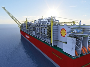 Shell’s Prelude project and lean FLNG. The first speaker, General Manager of Shell LNG Development for Shell Global Solutions International, Barend Pek, discussed Shell’s Prelude project in Australia—the first FLNG vessel scheduled to come into operation—as well as a new “lean FLNG” design Shell has developed for higher-capacity FLNG.
An FLNG project with a Prelude-like design is anticipated to produce 5.3 million tons per year (MMtpy) to 5.5 MMtpy of LNG, said Mr. Pek. However, Shell’s lean FLNG design will bring down the unit technical costs of FLNG projects by expanding liquefaction capacity, and it is a prime solution for lean gas fields. The technology involves simplified LNG extraction and the removal of the LPG extraction component. Lean FLNG also uses two trains instead of one, and a refrigerant import instead of refrigerant from its own feed. Aeroderivative gas turbines are incorporated into the lean FLNG design.
Mr. Pek noted that a side-by-side offloading system is a major improvement for FLNG projects, as it lowers stresses on the manifolds for LNG carriers and ensures successful offloading in harsh environmental conditions. Shell plans to continue development work to cater to larger and leaner gas fields, Mr. Pek said. Prelude is presently being assembled at the Samsung Heavy Industries yard.
During the Q&A session following Mr. Pek’s presentation, a conference attendee asked how CO2 emissions from FLNG compare to CO2 emissions from onshore LNG facilities. Mr. Pek noted that FLNG vessels will have the capability to remove CO2 from field gas and reinject it into reservoirs, although this option was not utilized for Prelude. However, Mr. Pek noted that the combined-heat-and-power-generation technology used for Prelude, along with the cooling water obtained from great sea depths, helps eliminate CO2 emissions, making the FLNG design as carbon-efficient as that of an onshore LNG facility.
Another audience member asked how maintenance shutdowns, which are extensive and time-consuming for onshore LNG plants, would be implemented on Prelude and other FLNG projects. Mr. Pek noted that continual maintenance would be carried out at Prelude during normal operations, unlike onshore LNG terminals, which normally shut down for maintenance. Prelude will house 110 workers during normal operations and will have the capacity to accommodate 150 people during maintenance periods.
Statoil’s Hammerfest inspires future FLNG. The next speaker, Dr. Jostein Pettersen, LNG technology advisor for Statoil ASA, spoke about technical and operational innovations for onshore LNG and FLNG. Dr. Pettersen briefly discussed the development of the Snøhvit gas field in the 1980s and the construction of the Hammerfest LNG plant, which he called “A pioneering development for Statoil, and certainly a challenging one in a lot of ways,” due to the harsh cold and darkness conditions in the Arctic climate of northern Norway.
Dr. Pettersen acknowledged that an FLNG vessel was originally considered for the Snøhvit field development, although an onshore LNG plant was ultimately chosen. The process facilities for the Hammerfest plant were built on a floating barge, which served as a predecessor for FLNG. The construction included a compact and modularized layout and prefabricated facilities, just as in FLNG design.
Statoil’s FLNG design concept, which has been under development since 1985 and for which feasibility, concept and pre-FEED studies have been completed, includes a double mixed-refrigerant (DMR) liquefaction process with mechanical compressor drivers and the option for side-by-side or tandem offloading. Lastly, Dr. Pettersen outlined three major areas of FLNG work on which Statoil is focusing:
--- Acid gas removal (to prevent freeze-out in the liquefaction process)
--- Offloading system selection
--- The large amounts of cooling water needed for operation.
Liquefaction technology selection for FLNG. Air Products and Chemicals Inc.’s Lead Process Engineer, Dr. Justin Bukowski, spoke about the selection of a liquefaction process for FLNG, which he called “a very basic and important choice to make when designing an LNG facility” and also “the heart of the LNG facility.”
Dr. Bukowski outlined several criteria for evaluating liquefaction processes for FLNG, including efficiency (i.e., LNG production capacity divided by the refrigeration power needed); train capacity (how much LNG can be produced at a single train); and equipment count (heat exchangers, precoolers, etc.). Dr. Bukowski pointed to weight, size and layout limits as important considerations. Wave- and wind-induced vessel motions dictate the mechanical strength requirements and the effects on two-phase flow in equipment.
Also, flammable inventory, such as propane tanks, may attract concerns from FLNG operators because it is difficult to separate living quarters from process areas. Corrosive marine environments pose additional challenges to successful, long-term FLNG operation.
To meet challenges, Dr. Bukowski offered several solutions, including robust equipment design and the appropriate selection of refrigeration technology. The process engineer recommended using coil wound heat exchangers (CWHEs) for safety and reliability, as they are proven to resist high thermal stresses. Also, the dual containment of leaks is achieved with tubes being located inside of the shell, which results in less downtime and more availability, as LNG operations can continue until maintenance can be performed to fix non-critical leaks.
Dr. Bukowski next outlined the pros and cons of four possible liquefaction processes for FLNG: DMR, single mixed-refrigerant (SMR), nitrogen (N2) recycle and precooled N2 recycle. Pre-cooled MR, such as the C3MR (propane-cooled) process, has the highest efficiency and a large capacity (5 MMtpy or more of LNG output), although the propane kettles needed for this process leave a large footprint. DMR, on the other hand, uses a second MR for precooling, and has the same efficiency and capacity as C3MR. However, with DMR, the propane inventory can be minimized at a small cost. For these processes, proper design of the CWHEs mitigates the effects of motion on two-phase flows.
The SMR process achieves precooling and liquefaction with the same refrigerant in a single exchanger. LNG production of 1 MMtpy–2 MMtpy can be achieved at a single train, which is around 87% of the C3MR/DMR process efficiency. Like C3MR and DMR, motion problems are eliminated with proper CWHE design.
Thirdly, the N2 recycle process is characterized by multiple turboexpanders, an all-vapor refrigerant, no motion sensitivity, higher flow rates and larger piping. LNG production is pegged at 1.5 MMtpy for a single train, or 75% of the C3MR/DMR process efficiency.
Lastly, precooled N2 recycle does not use a hydrocarbon refrigerant and can achieve LNG production of 2 MMtpy in a single train, or around 85% of the C3MR/DMR process efficiency. Motion is mitigated for both N2 recycle technologies with proper CWHE design.
In summary, Dr. Bukowski noted that all of the processes have advantages and disadvantages. “There are many processes, and they are all suitable for FLNG, and [the process choice] really depends on what [the customer] values” for the technology selection for the project, he said. Dr. Bukowski also explained that natural gas liquids (NGL) extraction in these processes can take place upstream, or it can be integrated downstream in the precooling scrub column.
Design methods for FLNG safety engineering. The last speaker on the panel, Technip risk assessment and quantification expert, Jérôme Hocquet, spoke to attendees about the safety studies undertaken for FLNG projects. Since FLNG is a “new” kind of facility, Mr. Hocquet said, it comes with new safety issues.
An FLNG vessel, which condenses the processes and equipment needed for an entire onshore LNG plant into one sixth of the space, is essentially a “congested” environment, Mr. Hocquet said. Therefore, the proximity of gas processing units to living quarters is a concern, as are the potential for gas leaks and explosions, the possible release of cryogenic material, and the potential for steel embrittlement.
Safety studies undertaken for FLNG facilities examine proper input to the design in the case of hazardous events, which ensures that personnel will be able to escape safely in the case of a major accident. Inherent safety principles, such as hazard prevention to reduce the likelihood of loss of containment and ignition, are also examined. Suitable fire protection, separation distances between personnel and equipment, and passive cryogenic protection for critical structures and equipment are other important components of such safety studies.
Mr. Hocquet concluded that a performance-based approach is the only proper approach for the safety engineering of FLNG to date, and it will remain the base until specific codes and standards are developed for the safety design of FLNGs. Over the last five years, Technip has completed several FLNG project studies and developed risk-based study methods to make FLNG vessels both safe and economically feasible.


Comments