
Digital Exclusive: Innovative grassroots CDU-VDU configuration—Pioneering energy efficiency and net-zero pathways in modern refineries
Authors: R. GORLE, S. GRANDHI, N. K. PALADUGU and A. KUMAR, Engineers India Ltd., New Delhi, India
In the evolving landscape of petroleum refining, where net-zero emissions targets are reshaping design paradigms, the crude distillation unit (CDU) and vacuum distillation unit (VDU) remain foundational, accounting for > 50% of distillate yields, including naphtha, kerosene, diesel and vacuum gasoils (VGOs). This article introduces a CDU-VDU configuration tailored for grassroots refineries, decoupling stripping and rectification sections via a dedicated flash drum to enable steam-free rectification. It avoids non-ideal vapor-liquid flashing at the flash zone and adds another fractionation stage there to minimize entrainment, thereby improving the quality of the lighter fractions above the flash zone by reducing entrained coloring and metal compounds from the bottom residue. By integrating a closed-loop high-temperature wash oil recirculation system—sourced from condensed stripper vapors—this design eliminates hydrocarbon dilution, boosts tray temperatures for superior heat integration and mitigates coking risks, achieving up to 40% steam savings and 16% power reductions without compromising throughput or product quality.
Validated on a 172,000-bpd BOPD Bombay High crude facility, this innovation yields an annual operational expenditure (OPEX) savings of $2.05 MM, a carbon dioxide (CO2) footprint reduction of 24,000 metric tpy (equivalent to 52.9 MM lb/yr), and enhanced flexibility for variable crude slates. For new-build projects, capital efficiencies arise from downsized columns (up to 4% weight reduction) and optimized ejectors. This configuration not only addresses energy-intensive legacy challenges but positions grassroots refineries as leaders in sustainable processing, aligning with global environmental, social and governance (ESG) imperatives. Detailed process flows, thermodynamic insights and economic analyses underscore its transformative potential as a technology for market expansion.
Background. The global refining sector, pivotal to energy security, processes > 100 MMbpd of crude into fuels and feedstocks that power economies. Yet, CDU and VDU operations—responsible for initial fractionation—consume ~30% of a refinery's total energy, primarily through fired heaters, steam generation and compression.1 As refiners target net-zero by 2050, grassroots designs must embed efficiency from inception, countering rising crude diversity, margin pressures and regulatory scrutiny on emissions.
In a typical CDU-VDU, the CDU separates lighter fractions at atmospheric pressure, while the VDU processes heavier residues under vacuum to produce VGO and vacuum residue (VR) without thermal cracking, as shown in FIG. 1.2,3 Crude oil is preheated to 250°C–300°C (482°F–572°F) via a heat exchanger network using heat from product streams and pumparound circuits, then heated to 340°C–370°C (644°F–698°F) in the CDU furnace before being flashed in a single column, where vapors rise and atmospheric residue settles. The integrated rectification zone refines vapors into naphtha, kerosene and diesel with reflux, while side-strippers remove lighter components. Steam injection at the bottom strips lighter hydrocarbons from the residue, boosting diesel yield but increasing vapor traffic.
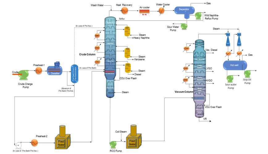
FIG. 1. Typical CDU-VDU configuration. (click image to enlarge)
The CDU residue [reduced crude oil (RCO)] is heated to 380°C–400°C (716°F–752°F) in the VDU furnace, processed under vacuum in a similar single-column design with an integrated rectification zone, using steam to strip lighters and produce vacuum diesel, VGO and VR. Overflash in both the CDU and VDU, generated by vaporizing a portion of the bottom product in the flash zone due to feed heating, supplies liquid for washing above the flash zone, returning as liquid to the bottom section to ensure clean diesel and heavy VGO (HVGO), respectively.4
Persistent challenges in conventional designs and the need for innovation. The use of steam in conventional CDU-VDU systems, while essential for stripping lighter components in the stripping zone, introduces significant hurdles when it migrates upward into the rectification section. This migration dilutes hydrocarbon vapors, requiring higher reflux rates and larger column diameters, which elevate both capital (CAPEX) and OPEX. In the CDU, the presence of steam lowers the dew point at the column top, rendering it susceptible to corrosion due to water condensation [promoting hydrochloric acid (HCl) corrosion from NaCl decomposition], particularly with temperature fluctuations. This necessitates frequent top tray replacements during maintenance and inspection (M&I) cycles, and occasionally requires cutting and replacing Monel-clad column top shell sections.5
In the VDU, operators face additional difficulties when processing diverse crudes beyond design specifications, particularly with overflash management. Prolonged adjustments to coil outlet temperature (COT) and unreliable overflash flowmeters lead to poor wetting from inconsistent liquid distribution. This results in zonal coking at the wash bed base, where dry spots foster heavy hydrocarbon adhesion and coke deposit formation. Uneven wetting triggers channeling and premature flooding, while temperature spikes of 54°F–90°F weaken metal sheets, causing coke lumps and scrambled sections.
These issues demand premature bed replacement every 2 yrs–3 yrs, compromising HVGO quality with color defects and escalating downtime costs. Additionally, managing entrainment requires drawing substantial unwanted slops above the flash zone to limit metals and coloring compounds in HVGO. In conventional crude and vacuum distillation processes, overflash and the slippage of light fractions into the bottoms—such as diesel slip or slop generation—are commonly practiced to address these risks. Operators handling opportunity crudes with uncertain COTs from fired heaters often maintain high overflash levels to mitigate diesel coloring issues, which also involves higher slippage of diesel into the RCO. This practice subsequently overloads the VDU’s rectification section, particularly the vacuum diesel circuit.
Similarly, in vacuum distillation, an increased flash zone vaporization rate (flash rate) requires proportionally higher slop draws to prevent contamination of the HVGO with metals, asphaltenes and color bodies. Because of the limited presence of lighter components in the vacuum residue (VR), these lighter fractions must be withdrawn as slop to control the light-end content of the VR and maintain its suitability as feed for the delayed coker unit (DCU).
Vacuum distillation units further encounter persistent challenges when handling reduced crude oil (RCO) and heavier fractions, aggravated by their reliance on steam to limit lighters in the vacuum residue. This steam, traditionally used to strip lighter components, generates excessive vapor traffic, straining overhead ejectors compounded by unintentionally stripped vacuum diesel components from the VDU top section.
In the stripping sections, sudden surges of medium-pressure (MP) stripping steam can mechanically stress the internals, potentially dislodging valves and tray panels. This not only disrupts vapor-liquid contact, but also degrades stripping efficiency, leading to slippage of lighter distillates into the bottom residue.
Since realignment or replacement of these tray panels can only be performed during a total plant shutdown, operators require due care to avoid steam pressure fluctuations. Low-pressure (LP) steam, while gentler, is generally avoided because its condensation within the column can wet light distillates and trigger pressure instabilities in the rectification zone.
Furthermore, as the name implies, the flash zone operates on a flash principle rather than true fractionation. Ideally, flashing separates lighter distillate fractions from the bottom residue; however, inefficiencies in the flashing process—exacerbated by entrainment from the feed inlet device—compromise this separation and contribute to the aforementioned issues.6
In contrast, dry distillation methods, which lack a dedicated stripping mechanism, require maintaining an even higher COT to prevent lighters from slipping into the bottom residue. This higher COT demands increased fired heater duty and elevates the risk of thermal cracking. As a result, effective fractionation across the flash zone remains elusive, perpetuating these operational risks and inefficiencies.7 Accordingly, novel technologies continue to evolve to enhance separation efficiency, reduce thermal severity and improve the overall operability of CDU–VDU units.8,9
The novel CDU-VDU configuration: A grassroots paradigm. The novel CDU-VDU configuration is engineered to redefine traditional distillation through structural and operational innovations. It decouples the stripping and rectification sections using a flash zone, allowing each to operate under optimized conditions (i.e., the stripper can be operated at a different pressure profile to optimize stripping efficiency, unlike the conventional design where the pressure below the flash zone is linked with the rectification section top pressure and pressure drop). This configuration combines the advantages of utilizing steam—considered one of the best stripping media—for stripping purposes, along with the adoption of a dry column configuration in the rectification section. Additionally, wash oil recirculation is integrated into the design. Moreover, steam optimization strategies are implemented, such as condensing stripping vapors in the VDU stripper overhead to separate hydrocarbons, enabling its use as pure steam to save stripping steam in the CDU-VDU strippers.10
Process flow and integration. The process flow is systematically depicted in FIG. 2.10 Crude oil enters the CDU, preheated via heat exchanger network using product streams and pumparound circuits, then heated in the furnace, flashed in the flash zone, with bottom liquid stripped in a separate stripper and vapors routed to a steam-free rectification column. The CDU residue (RCO) is sent to the VDU, using a similar steam-free rectification approach. In the VDU, the stripper overhead is connected to a separate ejector system to isolate hydrocarbons from the stripper overhead steam, which can be re-utilized as stripping steam. The closed-loop wash oil recirculation system is strategically deployed above the flash zone in the VDU wash section. This system repurposes condensed stripper vapors as high-temperature wash oil to ensure uniform wetting, enhancing reliability and preventing coking. By eliminating steam in the rectification zones of both the CDU and VDU and integrating this closed-loop system, the design mitigates coking, enhances heat integration and reduces energy consumption. Additionally, the condensed hydrocarbons from the stripper overheads of both the CDU and VDU contain minimal metal and coloring compounds, improving product quality, with further purity enhancement in the CDU stripping section through washing with stripping steam condensate.
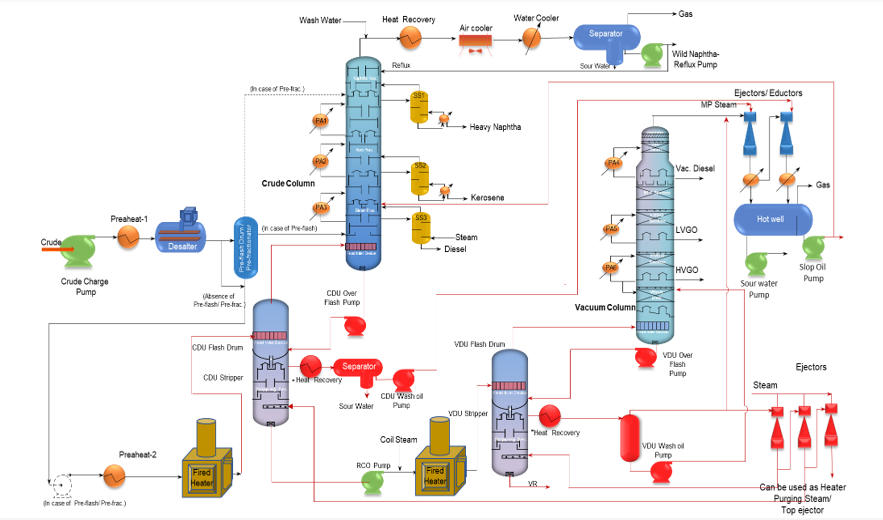
FIG. 2. Novel CDU-VDU configuration for a grassroots refinery. (click image to enlarge)
As illustrated in FIG. 2 with the dedicated flash drum, wash oil from the CDU stripper column can serve as a motive fluid in the last-stage ejector of the VDU top overhead, absorbing C3/C4 hydrocarbons from hotwell offgas (fuel gas) through a sponging effect, and is then returned to the CDU wash zone for hydrocarbon recovery. FIG. 2 builds on the conventional CDU-VDU scheme shown in FIG. 1, with additional details marked in red to emphasize the novel changes to be considered in a grassroot refinery CDU-VDU.
CASE STUDY: 172,000-BPD BOMBAY HIGH CRUDE REFINERY
A case study of a refinery operating with 172,000-bpd Bombay High crude, is considered as the Base Case. Operating conditions, including pressure, temperature and flowrate, were maintained in line with the Base Case, with product yields held within ±1% to ensure comparability. The steam-free rectification and wash oil system was established to optimize operating conditions. The broad product distillation and specification of the Base Case, considered for the new design, are shown in TABLES 1 and 2.
| Stream name | Unstable naphtha | Heavy naphtha | Light kero | Heavy kero | LGO |
| Total mass rate, lb/hr | 357,283 | 147,511 | 121,699 | 232,241 | 551,728 |
| Liquid standard density, lb/ft³ | 44.03 | 49.18 | 50.37 | 51.72 | 52.96 |
| ASTM D86 at 760 mmHG (LV) vs. °F | |||||
| 5% | 61.2 | 245.7 | 323.8 | 366.4 | 364.8 |
| 30% | 132.3 | 277 | 346.5 | 410.5 | 494.8 |
| 50% | 183.2 | 289.4 | 356.4 | 429.4 | 542.3 |
| 70% | 203 | 302.2 | 370.4 | 451.2 | 577.4 |
| 90% | 231.8 | 322.5 | 388.4 | 490.6 | 649.8 |
| 95% | 246.4 | 335.1 | 397 | 511.9 | 675.5 |
TABLE 1. Base Case details—CDU products
| Stream name | RCO | VAC diesel | LVGO | HVGO | VR |
| Total mass rate, lb/hr | 740,272 | 67,913 | 299,222 | 238,209 | 111,148 |
| Liquid standard density, lb/ft³ | 56.26 | 53.79 | 54.8 | 55.86 | 63.25 |
| ASTM D86 at 760 mmHG (LV) vs. °F | |||||
| 5% | 594.5 | 502.3 | 673.9 | 788 | 1,059.90 |
| 30% | 763.3 | 577.9 | 702.6 | 879.1 | 1,133.40 |
| 50% | 837 | 606.6 | 744.4 | 960.7 | 1,185.80 |
| 70% | 941.4 | 635.4 | 807.1 | 970 | 1,272.40 |
| 90% | 1,129.80 | 669.7 | 871 | 1,036 | 1,495 |
| 95% | 1,239.60 | 683.2 | 907.5 | 1,063.60 | 1,665.90 |
TABLE 2. Base Case details—VDU products
Results and discussion: Technical and economic depth. The novel configuration delivered transformative results: it achieved a 40% steam reduction (from 77,162 lb/hr to 46,297 lb/hr) and a 16% power reduction (from 2,247 kW to 1,892 kW), translating to $2.05 MM in annual OPEX savings, as shown in TABLES 3–6.
| Parameters | Units | Base Case | Optimum Case |
| CDU stripping steam | lb/hr | 19,401 | 18,739 |
| VDU stripping steam | lb/hr | 14,330 | 0 |
| VDU ejector steam | lb/hr | 43,122 | 27,602 |
| CDU and VDU pump duty | kW | 2,247 | 1,182 |
| Total | |||
| Steam | lb/hr | 77,162 | 46,297 (–40%) |
| Power | kW | 2,247 | 1,892 (–16%) |
TABLE 3. Comparison of Base Case and Optimum Case (utilities), OPEX Note: The conversion factors considered are—steam: 14 tons/MM tonnes of fuel oil equivalent (MTOE); power: 5,000 kw/MTOE; and cooling water: 20,000 m³/MTOE.
| Savings | Unit | Utility | MTOE |
| Steam | t/hr | 29,854 (MP) | 2,183 (LP) |
| Power | kWh | 355 | 0.071 |
| Fuel oil equivalent savings | MTOE/hr | 0.92 | |
| tpy | 7,384 | ||
| Savings in INR | $/t | 273 | |
| MM $U.S./yr | ~2.05 | ||
| CO2 savings | CO2 equivalent MMlb/yr | 52.9 | |
TABLE 4. Savings of utilities
| Parameter | Units | Base Case | Optimum Case |
| Column size (Dia. x Height) | |||
| CDU-Top section | ft | 22.0 x 187.5 | 21.3 x 187.5 |
| CDU-Bottom section | ft | 12.5 x 32.8 | 12.5 x 32.8 |
| CDU weight | lb | 1,433,003 | 1,395,524 (~2.6%) |
| VDU-Top section | ft | 22.3 x 31.7 | 22.3 x 31.7 |
| VDU-Middle section | ft | 32.8 x 137.8 | 30.5 x 137.8 |
| VDU-Bottom section | ft | 22.3 x 18 | 22.3 x 18 |
| VDU weight | lb | 1,461,663 | 1,399,934 (~4.2%) |
| Separators (Dia. x Length) | |||
| CDU stripper separator | ft | - | 4.9 x 11.8 |
| Stripper weight | lb | - | 13,228 |
TABLE 5. Comparison of Base Case and Optimum Case, CAPEX
| Parameters | Savings, $MM |
| OPEX savings | 2.05 |
| CAPEX difference | 0.32 |
| Total savings | 2.37 |
TABLE 6. Total savings, CAPEX and OPEX
Energy and environmental benefits. The steam-free rectification reduces vapor dilution and column traffic, achieving ~7,400 MTOE/yr of energy savings. It lowers the refinery’s carbon footprint by ~52.9 MM lb/yr of CO2 through reduced steam generation, aiding emissions compliance. Water use drops by 15% due to lower condenser duties, and demineralized water is saved by minimizing steam wastage, supporting resource conservation.
Eliminating steam in CDU and VDU rectification zones cuts vapor-liquid traffic and pressure drops, boosting heat recovery. This raises tray temperatures by 18°F–45°F, enabling deeper crude preheating and allowing products and pumparounds to be drawn at higher temperatures than conventional designs. The increased temperature differential reduces exchanger sizes in the preheat section, reducing fired heater duty and enhancing preheat efficiency.
High-temperature heat from the stripper overhead is recovered for processing, while low-grade heat preheats wash oil for the rectification column. Condensing stripper vapor at its dew point, with minimal non-condensables, maximizes heat transfer efficiency by reducing film resistance, as fresh vapor quickly contacts the heat transfer surface. Bottom pumparound (BPA) duty is shifted to the stripper condenser, where higher temperatures enable more efficient duty extraction in crude preheat compared to conventional BPA draw points.
Steam savings/ejector system optimization. Condensing stripping steam in the VDU stripper overhead separates hydrocarbons (mainly HVGO with minimal lighter gases), leaving pure steam with < 0.5% non-condensable hydrocarbons. This steam is reused for stripping or heater purging. The absence of stripping steam reduces the VDU top vapor condensable load, cutting ejector motive steam demand by 15%–30%. Additionally, integrating VDU stripping column steam into the CDU saves 5%–10% of its stripping steam.
Distillation operation/efficiency. Top vapor generation is reduced in both the CDU and VDU, enhancing efficiency as the absence of steam improves rectification zone fractionation by avoiding irrelevant material dilution. Approximately 8% additional vacuum diesel is recovered, reducing slop rerouting. More over-flash liquid is drawn without extra energy (at the same COT as the Base Case), eliminating metering issues when pumped mechanically instead of relying on gravity flow.
The stripper can be operated at lower pressure than the rectification zone, improving stripping efficiency and utilizing excess LP steam (instead of MP steam) while lowering fired heater COT. As it adds an additional fractionation stage to the flash zone with good wetting rates, overflash and COT can be reduced. The stripper can be isolated for maintenance by replacing the tray panels for efficient stripping while the rectification column continues operating. Unlike dry fractionation, effective stripping means it does not depend on higher overflash or COT to minimize slippage of lighter distillates into the bottom residue.
Successive dual flash zones (optional)—one in the flash drum and one in the rectification column—optimize separation. Reduced lighter components in bottoms lessen downstream unit loads, and VDU stripper bottom temperatures drop by ~18°F due to low-pressure operation, minimizing quenching needs to prevent coking. Vapor load distribution between rectification and stripper overheads enhances equipment sizing flexibility. The present shift to reboiler side strippers from steam side strippers for dry distillate products and operational stability further enables a steam-free rectification section.
Wash bed performance and coking mitigation. The closed-loop wash oil system, deployed above the CDU and VDU flash zones, addresses operational bottlenecks by optimizing overflash at the same COT. Using high-temperature wash oil, it ensures consistent wetting, reduces temperature variations, boosts HVGO yield by 2%–3%, lowers COT, minimizes slop formation and enhances stability, especially with high-asphaltene crudes.
Recycled wash oil outperforms slop, which can reduce HVGO yield or introduce contaminants, requiring higher COT. The closed-loop system maintains effective wetting without impacting HVGO yield or raising COT, improving process performance. At the same COT, increased overflash indicates better wetting, while improved end-point distillation of diesel and HVGO reflects enhanced fractionation and metal washing.
The system replaces traditional overflash washing, reducing coking risks by minimizing metal, solids and coloring compound buildup. The unique closed-loop self-washes with condensed water and fresh stripping zone vapor (by adding additional fractionation stage), preventing metal, salt and coloring compound accumulation.
Hydraulic and operational enhancements. Reduced vapor-liquid traffic decreases jet flood by 15%–20% and pressure drop by 20%–25%, allowing smaller column diameters or 5%–10% throughput increases. In the VDU, the hydrocarbon vapor load to ejectors drops by 20%–30%, cutting motive steam demand from 26,455 lb/hr to 17,637 lb/hr (15%–30% reduction), improving vacuum efficiency. Dual flash zones—one in the flash drum and one in the rectification column—optimize separation and minimize entrainment. Additionally, the VDU recovers 20%–30% of vapor load as vacuum diesel, enhancing pumparound duty.
Corrosion and reliability. Eliminating steam in rectification raises the CDU top dew point by 18°C–27°C, reducing water condensation and corrosion, thus extending equipment life. The wash oil system minimizes wash zone fouling, enhancing reliability and reducing unplanned shutdowns, especially with variable crudes. In the CDU stripper overhead, the closed-loop system self-washes with condensed water and fresh stripping zone vapor, preventing salt accumulation in the rectification wash zone. This reduces NaCl decomposition into HCl at higher temperatures, further mitigating CDU top section corrosion.
Economic impact. The $2.37-MM savings include $2.05 MM from utility reductions and $0.32 MM from CAPEX savings in greenfield designs due to smaller column diameters and efficient ejectors. This translates to a payback period of < 2 yrs for retrofit investments, remaining robust despite utility price fluctuations.
Retrofit feasibility and implementation. The retrofit-friendly design required minimal modifications, including chimney tray blanking and nozzle additions, implementable during 30-d to 45-d shutdowns. The design’s flexibility to increase throughput by 5%–10% offers additional revenue, particularly for processing high-contaminant crudes.
Strategic implications. This configuration positions refineries to meet net-zero targets while enhancing profitability. As a licensable technology, it offers a strategic advantage, aligning with ESG criteria that influence market competitiveness. The design’s adaptability to evolving crude slates and regulatory frameworks ensures long-term relevance, potentially attracting technology-driven refiners seeking sustainable solutions.
Takeaways. This grassroots CDU-VDU innovation—by prioritizing heat recovery and fouling mitigation—achieves 40% steam and 16% power savings, an annual $2.05-MM reduction in OPEX, and a 52.9 MM lb/yr reduction in CO2 in a typical 172,000-bpd Bombay High crude refinery. Being Bombay High, a light crude of API > 38°, the innovation yielded remarkable benefits; whereas for heavy crudes (where stripping is more crucial and the high steam-consuming stripping section dominates), this configuration will certainly add even more value to unit energy optimization.
It also offers a blueprint for eco-efficient new builds with the potential for increased throughput studies across opportunity crudes, redefining distillation for the net-zero era. Through vapor load recovery, wash recirculation and dry rectification—which avoids non-ideal vapor-liquid flash at the flash zone and adds another fractionation stage at the flash zone to minimize entrainment and improve the quality of the lighter fractionation above the flash zone by minimizing entrained coloring and metal compounds from the bottom residue—it boosts yields by 2%–3%, reliability by 20%–30%, and flexibility. As refiners build new units, this configuration delivers profitability and sustainability, heralding enhanced performance and operational excellence. In an era of geopolitical crude volatility and carbon pricing mechanisms, such innovations are not merely optional, but essential for maintaining competitive margins while advancing decarbonization agendas.
LITERATURE CITED
1 Szklo, A. and R. Schaeffer, “Fuel specification, energy consumption and CO2 emission in oil refineries,” Energy , Vol. 32, pp. 1075–1092, July 2007.
2 Fahim, M. A., T. A. Al-Sahhaf and A. Elkilani, Fundamentals of petroleum refining, Elsevier Science, 2010.
3 Hsu, C. S. and P. R. Robinson, Springer handbook of petroleum technology, Springer, 2017.
4 Gary, J. H., G.E. Handwerk and M. J. Kaiser, Petroleum refining: Technology and economics, 5th Ed., CRC Press, Boca Raton, Florida (U.S.), 2007.
5 Golden, S., T. Barletta and S. White, “Designing the CDU/VDU for opportunity crudes,” Sour & Heavy, 2012, online: https://static1.squarespace.com/static/5c92ba8e01232c369bea6695/t/5d9f75f8c9a1133d1b1cc2da/1570731512511/Designing+the+CDU+VDU+for+opportunity+crudes.pdf
6 Bagajewicz, M. J., “Design of crude fractionation units with preflashing or prefractionation: Energy targeting,” Industrial & Engineering Chemistry Research, Vol. 41, May 2002.
7 Waheed, M. A. and A. O. Oni, “Performance improvement of a crude oil distillation unit,” Applied Thermal Engineering, Vol. 75, pp. 315–324, January 2015.
8 Kumar, S., N. S. Madhusudan and M. O. Garg, “Method for increasing gas oil yield and energy efficiency in crude oil distillation,” U.S. Patent 9,546,324 B2, 2017.
9 Pradeep, P. R., S. K. Das, T. H. V. D. Prasad, A. K. Kumar, R. Rajesh, M. P. K. Kumar, D. Bhattacharyya, S. K. Mazumdar and S. S. V. Ramakumar, “Process for conversion of high acidic crude oils,” U.S. Patent Application 2019/0225892 A1, 2019.
10 Indian Patent Application No. 202311020036, “A distillation system for separating components of crude oil, Engineers India Ltd., 2023.
ABOUT THE AUTHORS
Ramanayya Gorle is a Senior Manager at Engineers India Ltd. (EIL), New Delhi, with more than 15 yrs of experience in process design, development and commissioning for the oil and gas and refining sectors. His expertise spans mass transfer equipment, column hydraulics, desalters, heat exchangers, fired heaters and heater treaters, with a strong focus on energy efficiency and process intensification.
He has led several high-impact innovations, including patented CDU–VDU configurations achieving nearly 50% reduction in VDU steam consumption, a novel single-column sour water stripping (SWS) unit with ~30% lower energy use and complete H₂S–NH₃ separation, advanced AC–DC crude desalting technology, syngas scrubbing systems, and 2G bioethanol distillation processes. He is credited with more than 15 patent applications.
Gorle has contributed extensively to digital twin development, real-time optimization and the deployment of EIL’s proprietary technologies—such as indDiesel®, indDSK®, and indJet®—improving refinery operability and sustainability. His project experience includes refinery process optimization, CDU reflux drum innovation, desalter revamps for BPCL, IOCL, BORL and CPCL, and heater treater design for ONGC. A Certified Energy Manager and Auditor, he holds a B.Tech in chemical engineering from Andhra University and is proficient in PRO-II, ASPEN, FRI and HTRI.

Srivardhan G is an Assistant General Manager in R&D at Engineers India Ltd. (EIL), New Delhi, with more than 15 yrs of experience in computational fluid dynamics (CFD), coal-to-liquids (CTL), refinery and petrochemical technology development, and energy efficiency improvement studies. His work also extends to biomass valorization and sustainable process development.
He has played a key role in developing several high-impact process innovations, including a novel CDU–VDU configuration delivering nearly 50% reduction in VDU steam consumption and a single-column SWS unit achieving ~30% lower energy consumption with complete H₂S–NH₃ separation. He is credited with more than 20 patent applications, of which 10 have been granted, along with three international publications.
A BEE-certified Energy Auditor, Srivardhan is a recipient of the Ambuja Young Researcher Award and the National 2nd Runner-Up prize in the NHRDN Business Simulation Competition (2016). He has actively contributed to more than 50 national and international conferences, including the World Petroleum Congress held in Istanbul, the U.S. and Canada.
He holds a postgraduate degree in chemical engineering from IIT Kanpur.

Narendra Kumar Paladugu holds a Master of Technology in chemical engineering from NIT Tiruchirappalli and has been associated with Engineers India Ltd. (EIL) for more than 19 yrs. His professional expertise spans process simulation, in-house software development, coal gasification and renewable energy systems.
He has been actively involved in the development and deployment of indigenous process tools and technologies, contributing to both conventional hydrocarbon processing and emerging energy transition domains. Paladugu has also represented EIL at several national and international technical conferences, sharing insights on process innovation and sustainable engineering solutions.
His long-standing experience and cross-domain proficiency continue to support EIL’s efforts in advancing efficient, reliable and future-ready process technologies.

Anil Kumar is the Executive Director (Technical) at Engineers India Ltd. (EIL), New Delhi, with more than 31 yrs of experience in process design, technology development and plant commissioning across the oil and gas, refining and petrochemical sectors. His career has been rooted in translating refinery concepts into operating assets, with a strong grounding in both design fundamentals and operational realities.
His expertise spans crude oil distillation, hydrotreating, hydrocracking and complex refinery configurations, with particular strength in refinery configuration studies and LP-based optimization modeling to evaluate feedstock flexibility, product slate optimization and energy efficiency. He has served as Group Lead and Technical Authority for several large and complex projects, including Dangote Refinery, HMEL, GAIL, etc., contributing across the full project lifecycle from early configuration studies to commissioning support.
Currently, he heads the R&D Division at EIL, leading indigenous technology development, process innovation and intellectual property creation, with a focus on improving refinery performance and addressing emerging energy-transition challenges.
Kumar holds a B.Tech in chemical engineering from Banaras Hindu University.


Comments