
Digital Exclusive: Root cause analysis on hydrochloric acid corrosion in a diesel hydrotreater unit
J. A. MONTILLA RODRIGUEZ and S. IDRISSI, Saudi Aramco, Dhahran, Saudi Arabia
This article presents the findings from an investigation report following the discovery of severe corrosion in the oxygen stripper condensers of a diesel hydrotreater (DHT). A root cause analysis was conducted by a multi-disciplinary team, which identified three causal factors:
- The ingress of inorganic chlorides into the DHT’s feed from the vacuum diesel oil stream
- The use of steam as a stripping medium for the oxygen stripper
- The absence of a sample point on the sour water stream.
The analysis revealed that the root cause of the failure was an inadequate design of the oxygen stripper, which failed to account for the unanticipated presence of chlorides from the vacuum distillation unit. The recommendations outlined in this article aim to mitigate this issue by introducing a corrosion control chemical and upgrading the metallurgy of the affected condensers.
Corrosion control. Corrosion control is one of the main concerns in refineries. An unexpected leak due to improper control represents a risk of flammable hydrocarbon release, with consequences that may vary from production reduction, unplanned shutdown for repairs and even fatalities. For crude atmospheric distillation process units, hydrochloric acid corrosion and salt formation are typical corrosion mechanisms that need to be prevented.1–5 Analysis of several parameters—mainly pH, iron and chlorides—in the condensed sour water provide good indicators on the effectiveness of current corrosion control techniques. Similar corrosion issues have also been observed in downstream units, such as DHTs, where the environment for hydrochloric acid condensation may be promoted. Similarly, chloride control in DHTs is required.7 FIG. 1 shows a typical crude and vacuum distillation column unit (CDU/VDU), along with the DHT feed system that is discussed in this article.
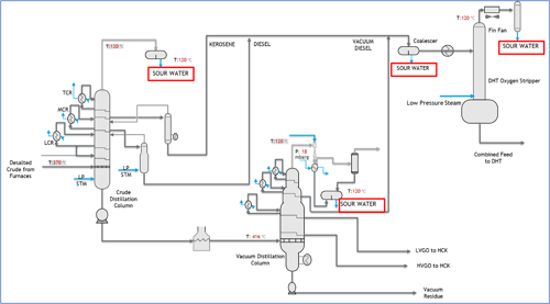
FIG. 1. Diagram of a typical crude and vacuum distillation column.
The crude that feeds the distillation column unit contains primarily three types of inorganic chlorides: magnesium chloride, calcium Chloride and sodium chloride.1,4 The hydrolysis of these salts will generate hydrogen chloride (HCl) gas that will travel to the column overhead. Once the water dewpoint is reached, HCl will condense as hydrochloric acid, which is extremely corrosive, reaching pH as low as 1–2.1 The reason for this is because at the initial dewpoint, the quantity of water is minimal, with a very high concentration of HCl. The overhead systems in atmospheric and vacuum columns provide the required temperature and pressure conditions to reach the dewpoint.
The hydrolysis for each case occurs at different temperatures, as shown in TABLE 1.
TABLE 1. Hydrolysis reactions1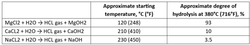
The maximum heater outlet temperature in crude atmospheric columns is around 380°C (716°F).
There are several sources of corrosion and contaminants that may be contained in the crude, either naturally or during its extraction. It has long been recognized that certain additives used in oil and gas production field development and operations can impact downstream refining processes.2 Corrosion control typically starts with the storage tanks by proper dewatering.4 After the crude is introduced into the CDU, the crude is sent to a desalter. The desalter will significantly remove the contaminants through the desalter brine. Crude oil is mixed with wash water to remove most of the inorganic contaminants (e.g., salts) and solids, typically at temperatures between 100°C–150°C, and water contents of approximately 5 vol%, including injection of chemicals such as demulsifiers to avoid emulsion formation or chemicals to control the pH of the desalter water. The oil and water phases are separated in the desalter where most salts and sediments leave the vessel together with the water phase.4 The desalter will eliminate most salts mentioned in TABLE 1; however, it is not 100 % efficient.1 The typical amount of salts is 1 pound per thousand barrels in the outlet of the desalter, which indicates that small amount of chlorides will remain in the crude.
Caustic is used for chloride control in the CDU’s overhead system. As indicated in TABLE 1, sodium chloride (NaCl) starts to hydrolyze at 230°C at a very low rate. Similarly, at the highest heater outlet temperature (380°C), NaCl had hydrolyzed only 3.5%. For this reason, caustic [sodium hydroxide (NaOH)] is used downstream of the desalter to transform the HCl and the residual inorganic salts that might be hydrolyzed into stable NaCl.1,5 In other words, the use of caustic will not eliminate chloride but rather convert it into a salt that will not cause corrosion in the CDU overhead system due to the high hydrolysis temperature. The reactions involved are shown in Eqs. 1–3:
MgCl2 + 2NaOH → Mg (OH)2 + 2NaCl (1)
CaCl2 + 2NaOH → Mg (OH)2 + 2NaCl (2)
NaOH + HCL → NaCl + H2O (3)
This article discusses the outcomes from an investigation report regarding unexpected leaks because of corrosion in the DHT’s oxygen stripper overhead condensers. The failure created unexpected shutdowns and reductions in refinery capacity.
The DHT’s feed is a blend consisting of hot streams directly from the CDU/VDU—i.e., kerosene, diesel and vacuum diesel oil (VDO). Additional diesel from storage tanks, used as cold feed, is part of the blend, as well. The combined feed is then sent to a coalescer to remove free water. Downstream of the coalescer is an oxygen stripper (FIG. 1).
The objective of the oxygen stripper is to remove any dissolved oxygen in the diesel coming from the storage tanks (cold feed). The combined diesel feed (a mix of hot and cold streams) is introduced to the oxygen stripper at 200°C, where the stripping media is the low-pressure steam. The low-pressure steam strips out the oxygen, any dissolved water and light hydrocarbons to the overhead system.
FIG. 2 shows the findings in one of the overhead condenser banks, where 56 tubes were found with < 40% defect and 90 tubes with a 20% defect. The material is carbon steel.
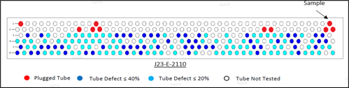
FIG. 2. Condenser inspection findings.
FIG. 3 shows the reduced thickness of the tube sample, with a minimum of 0.6 mm vs. a designed thickness of 2.108 mm.
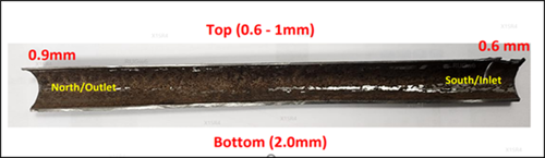
FIG. 3. Reduced thickness in the tube.
Root cause analysis (RCA) methodology. A multi-disciplinary team was formed. This team followed the RCA approach FIG. 4. The team collected data associated with the event to identify causal factors. Subsequently, for each causal factor, the team analyzed and developed the root causes to provide recommendations aiming to avoid a recurrence.
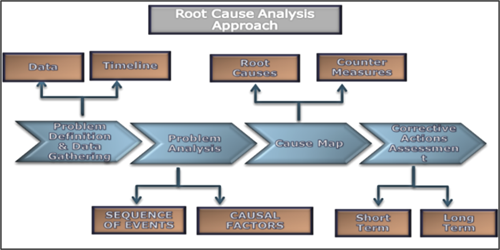
FIG. 4. The RCA approach.
RCA discussions and results. The team identified two potential areas to find the causal factors: hydrochloric acid corrosion and design aspects. FIG. 5 shows the causal factors chart.
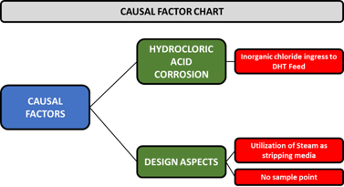
FIG. 5. The casual factor chart.
Hydrochloric acid corrosion. During the investigation, it was required to collect sour water samples from the DHT’s feed coalescer and oxygen stripper overhead drains. There was no sample point installed nor sampling routine. FIG. 6 shows chlorides in the order of 400 parts per million (ppm)–500 pm, and iron levels averaging 100 ppm. For the overhead sample (FIG. 7), the chlorides are in the order of 80 ppm–100 ppm, while the iron content is around 5.5 ppm–20 ppm. The typical maximum control for chlorides and iron in sour water samples are 30 ppm and 1 ppm, respectively.
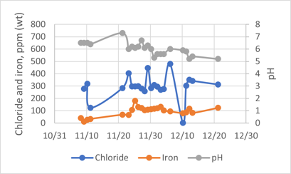
FIG. 6. Sour water from the DHT’s feed coalescer.
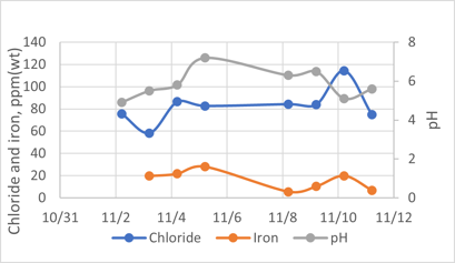
FIG. 7. Sour water from the DHT’s oxygen stripper overhead.
A sample of the affected tube was sent to the lab for metallurgical analysis. Unfortunately, the sample was taken after the tubes were hydro-jetted, which removed corrosion products; therefore, no high chloride levels were found. However, the high metal loss corrosion rate, corrosion morphology, the shape of the damage on the internal diameter and the concentration of corrosion on the top side of the tube suggested that condensation of the fluid caused the damage (FIG. 3).
Samples of the feed components were sent to the lab to check for chlorides using the ASTM-7536 method. The results are shown in TABLE 2.
TABLE 2. Chloride content in the streams feeding the DHT
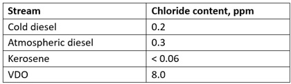
In CDUs, caustic is added typically after the desalter to react with the chloride present in the crude oil stream to form NaCl.1 Due to the high hydrolyzation temperature, NaCl is normally carried downstream.3 Consequently, the atmospheric residue at the bottom of the atmospheric crude column contains NaCl, and partial hydrolyzation to HCl vapors occurs in the vacuum column. A minimum amount of HCl is contained in the VDO feed stream to the DHT, as shown in TABLE 2. The decrease in temperature in the oxygen stripper, along with presence of water from the condensation of low-pressure steam used as stripping media, created the environment to condense HCl vapors into very corrosive hydrochloric acid. According to the chloride balance that was conducted, 0.5 ppm of inorganic chlorides in the feed will result in 100 ppm in the oxygen stripper overhead sour water.
HCl does not cause corrosion problems at temperatures above the aqueous dewpoint.1 As the temperature reduces, there is a risk to reach the water dewpoint and HCl condensation. This phenomenon is enhanced due to the presence of oxygen. Dissolved oxygen, even in small concentrations, often drastically increases the corrosion of carbon steel.1
TABLE 2 indicates that the hot VDO has a higher chloride content compared to the other streams. The vacuum column evaluated in this analysis operates without stripping steam, whereas the atmospheric column utilizes stripping steam. Since the vacuum column contains only a minimal amount of steam, the partial pressure of HCl increases, resulting in a higher concentration in the liquid streams. This finding is consistent with Henry's Law, which states that "at a constant temperature, the amount of a given gas that dissolves in a given type and volume of liquid is directly proportional to the partial pressure of that gas in equilibrium with that liquid."
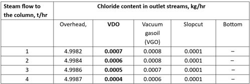
To assess the potential effects of introducing steam into the column on the chloride content of the outlet streams, a chloride balance was performed within the vacuum column. This evaluation was conducted using a proprietary simulation modela, which enabled the systematic introduction of stripping steam at various flowrates. As shown in TABLE 3, increasing the steam flowrate from 1 t/hr to 4 t/hr resulted in a reduction in chloride concentration from 7 ppm to 4 ppm in the VDO. This explains why the VDO stream has a higher concentration of HCl compared to the other streams in the CDU.
TABLE 3. Chloride content in the vacuum column’s outlet streams
Design aspects.
Utilization of steam as stripping media for the oxygen stripper. Wet stripping media is another causal factor for the condenser tubes failure, as it promotes an aqueous environment due to the steam condensation in the presence of HCl from the hydrocarbon streams.
No sample point for the oxygen stripper overhead sour water. The absence of corrosion control measures, resulting from the lack of a sample point to analyze the sour water, is another contributing factor to the condenser tubes' failure. If a routine analysis of the sour water for pH, chloride and iron had been in place, the problem could have been identified at an early stage. However, the condenser tubes had been corroding since the unit's initial startup, but the issue went undetected until the failure occurred. The corrosion mechanism confirmed after inspection is consistent with hydrochloric acidic corrosion.
Operating parameters. Since the oxygen stripper was operated in accordance with its design, with low temperatures in the overhead, its operating parameters are not considered a causal factor.
The root cause of failure. Mapping of the root cause is detailed in FIG. 8. From the causal factor analysis, the root cause of the tube leak is attributed to the inadequate design of the oxygen stripper.
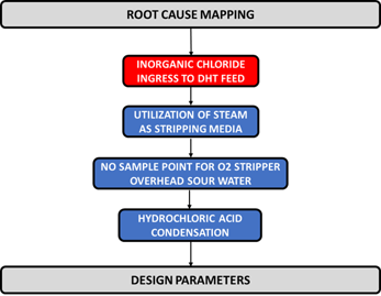
FIG. 8. Root cause mapping of the tube leak.
Takeaways and recommendations. The RCA team concluded that the failure in the exchanger was attributed to design deficiency that led to hydrochloric acid corrosion. A minimal amount of HCl is present in the VDO stream that feeds the DHT. The decrease in temperature in the oxygen stripper’s overhead, combined with the presence of water from the condensation of low-pressure steam used as a stripping medium in the condensers, created an environment conducive to the condensation of HCl vapors into highly corrosive hydrochloric acid. The absence of a sample point, coupled with the use of inadequate materials, rendered the coolers susceptible to leakage, a vulnerability that was not identified during the design phase of the DHT. The corrosion mechanism, as confirmed by the inspection, was consistent with hydrochloric acid corrosion.
The team recommended the following to avoid re-occurrence:
- Evaluate using dry stripping media for the oxygen stripper instead of steam to minimize the impact of chlorides in the overhead system.
- Install a sample point at the oxygen stripper’s overhead system to analyze sour water.
- Evaluate the option of either applying a chemical treatment program or upgrading the metallurgy of condensers (header, tubes and plugs) from carbon steel to nickel alloy 825.
DECLARATION OF COMPETING INTEREST
The authors declare that they have no known competing financial interests or personal relationships that could have appeared to influence the work reported in this article.
ACKNOWLEDGEMENT
The authors are grateful to Saudi Aramco for the great privilege and honor to work on this task.
NOTE
a Aspen HYSYS
REFERENCES
1 Wills, K. A., K. O. Sarpong, “Survey on crude unit overhead corrosion control practices,” NACE International (now AMPP), CORROSION 2019, Nashville, Tennessee, March 2019, online: https://onepetro.org/NACECORR/proceedings-abstract/CORR19/CORR19/NACE-2019-13109/127305
2 NACE technical committee, “Potential effects of upstream additives on refinery corrosion and fouling,” NACE International (now AMPP), January 2017.
3 Patel, K., “Mitigating overhead corrosion and reducing downstream costs,” PTQ, Q4 2021, online: https://cdn.digitalrefining.com/data/articles/file/1002721-q4-suez.pdf
4 Schempp, P., et al., “Corrosion in the crude distillation unit overhead line: Contributors and solutions,” European Federation of Corrosion, online: http://eurocorr.efcweb.org/2017/abstracts/13/88826.pdf
5 Mahajanam, S., F. Addington and A. Barba, “Underdeposit corrosion in crude tower overheads,” NACE (now AMPP) CORROSION 2017, New Orleans, Louisiana, 2017.
6 NACE, “Standard practice: Refinery injection and process mix points,” NACE International (now AMPP), June 6, 2014.
7 Shargay, C. A., et al., “Design considerations to minimize ammonium chloride corrosion in hydrotreater REAC’s,” NACE (now AMPP) CORROSION 2001, Houston, Texas, 2001.
The Authors

Jesus A. Montilla Rodriguez is a seasoned Process Engineer with > 20 yrs of experience in the oil and gas industry. Currently, he serves as a Process Engineer Specialist at Saudi Aramco Engineering Services in Dhahran, Saudi Arabia. Throughout his career, he has gained extensive expertise in crude and vacuum distillation units, encompassing all project phases, commissioning and normal operation. His expertise also includes performance optimization, troubleshooting, debottlenecking and the development of engineering solutions. He earned a chemical engineering degree from the Universidad de Carabobo in Venezuela.

Salahdine El Idrissi is a Process Specialist in hydroprocessing at Saudi Aramco Engineering Services in Dhahran, Saudi Arabia. He earned a degree in Energy and Processes from the Institut National Polytechnique de Grenoble, France. With > 15 yrs of experience in the oil and gas industry, El Idrissi has developed expertise in hydroprocessing technologies, including hydrotreating, hydrocracking and catalysis. His areas of specialization includes process design and optimization, troubleshooting and debottlenecking, and the development and deployment of new technologies to improve refinery performance and profitability.


Comments